
Remark: “The Select CCT Type” radio button and the “Add CCT Type from Library to Project” button should not be used anymore. You may access the function block diagram directly through the popupmenu by clicking the right mouse button on the CCT element. The functions block may be accessed wit menu item “Insert”. You may now insert your CCT with function blocks. NEPLAN User's Guide V5Ī “CCT” dialog appears. Click in the diagram near a synchronous machine to enter the CCT. Then you may with the right mouse button directly open the diagram through the popup menu (popup menu item “Subsystem”).

A nested CCT element may be entered first. Normally you will design this CCT in a separate NEPLAN diagram. These predefined NEPLAN regulator types are optimized for the NEPLAN simulator.Įnter a user defined CCT with function blocks NEPLAN allows entering a user defined CCT in a very comfortable way with the help of a function block editor. Once again: if a predefined type is available you should use this standard type. 16.2 Insert graphically a predefined NEPLAN standard exciter
Neplan tutorial generator#
16.1 Generator dialog: Assign a predefined NEPLAN standard exciter to the generatorįig. You may also add the exciter first graphically (see above).įig. The exciter will then not appear on the single line diagram. If the exciter is not yet in the network you may add and edit the exciter directly in the synchronous machine dialog. You may assign an exciter to a generator in the dialog below with the button “…”. You find the regulator symbol in the “Symbol Window -> FACTS/DC/Specials”. You have to enter the standard regulator just like any other element in the network.
Neplan tutorial how to#
Below is a detailed description of how to add an exciter to a generator.

Then you have to assign the regulator (e.g. generator) into the network (single line diagram). exciter) and the controlled element (e.g. This is the preferred and easiest way to enter an exciter! You have to insert regulator (e.g.
Neplan tutorial simulator#
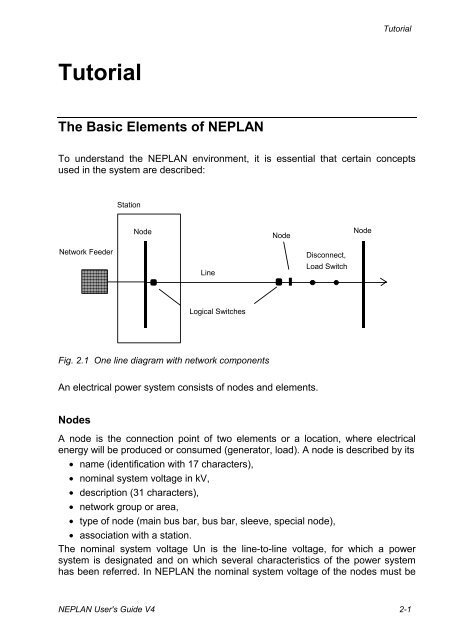
Tutorial - NEPLAN Simulator Introduction This module substitutes the Transient Stability PROST, which is described in section Transient Stability and the normal Tutorial.


 0 kommentar(er)
